Introduction
Bézier curves have been a fascinating and intriguing concept to me. Simply put, Bézier curves allow us to define curves using mathematical equations. Harnessing these equations to bend the curves to our will can be daunting for those who are unfamiliar with the concept. If you wish to know about Bézier curves in details, look at this excellent tutorial on Bézier Curves.
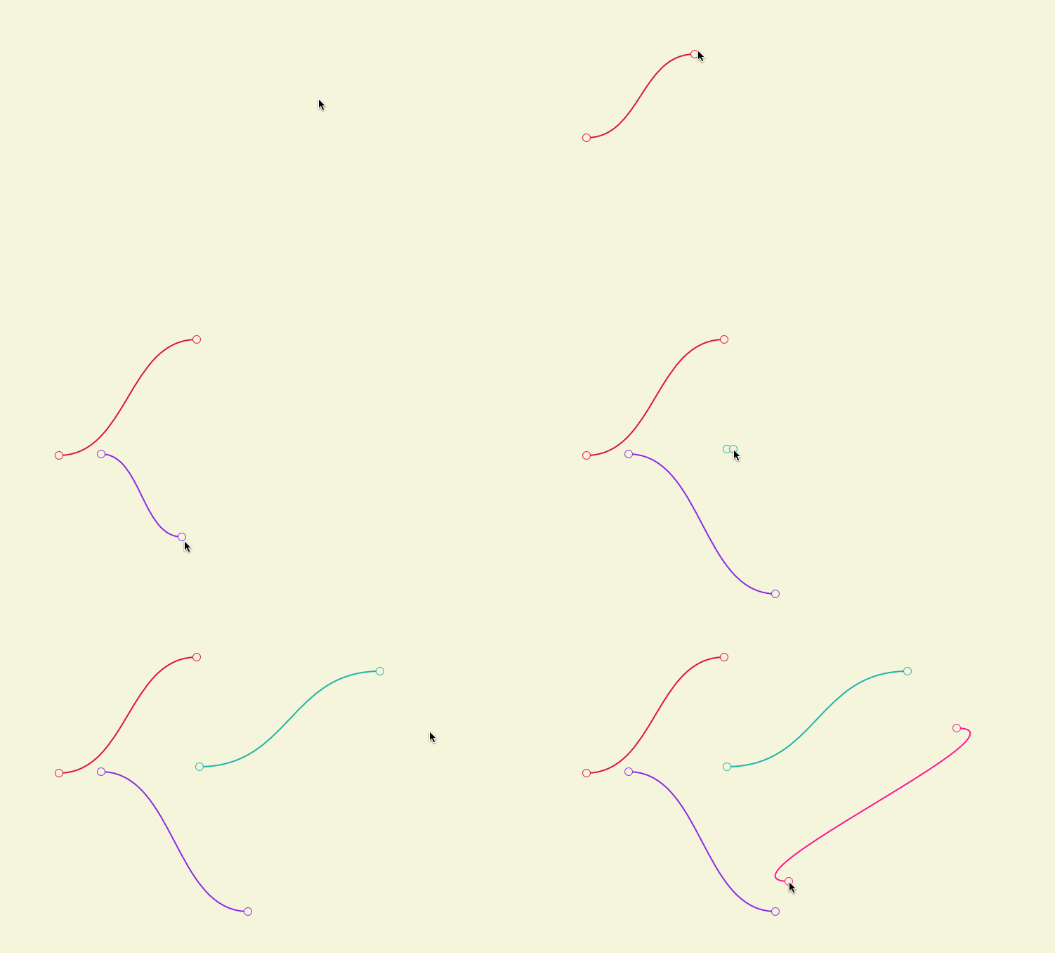
Often, I have come across node graphs which show a set of nodes connected together, not by straight lines but nice curved lines. The curved lines give the graph a more sophisticated look. Here is a cool example of connectors used in BitWig Studio 3.
If you moved the nodes around, the curved lines adjusted their curvature accordingly. Initially I thought that, to accomplish this, some really complicated mathematical calculations need to be done to get the precise curvature in the connectors. However, when I gave it a closer look, I realized it was a simple Cubic Bézier. In this post I will tell you how I achieved this

Cubic Bézier
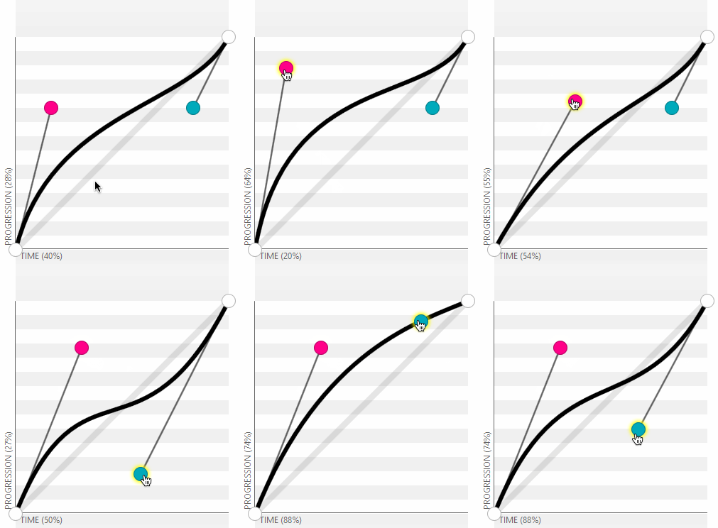
To define a cubic bézier, you need four points – two endpoints and two control points. The curve will always pass through the endpoints while they may or may not pass through the control points. The control points influence the curvature (see the image below).

(The above image was created from this awesome site.)
Creating a Cubic Bézier connector
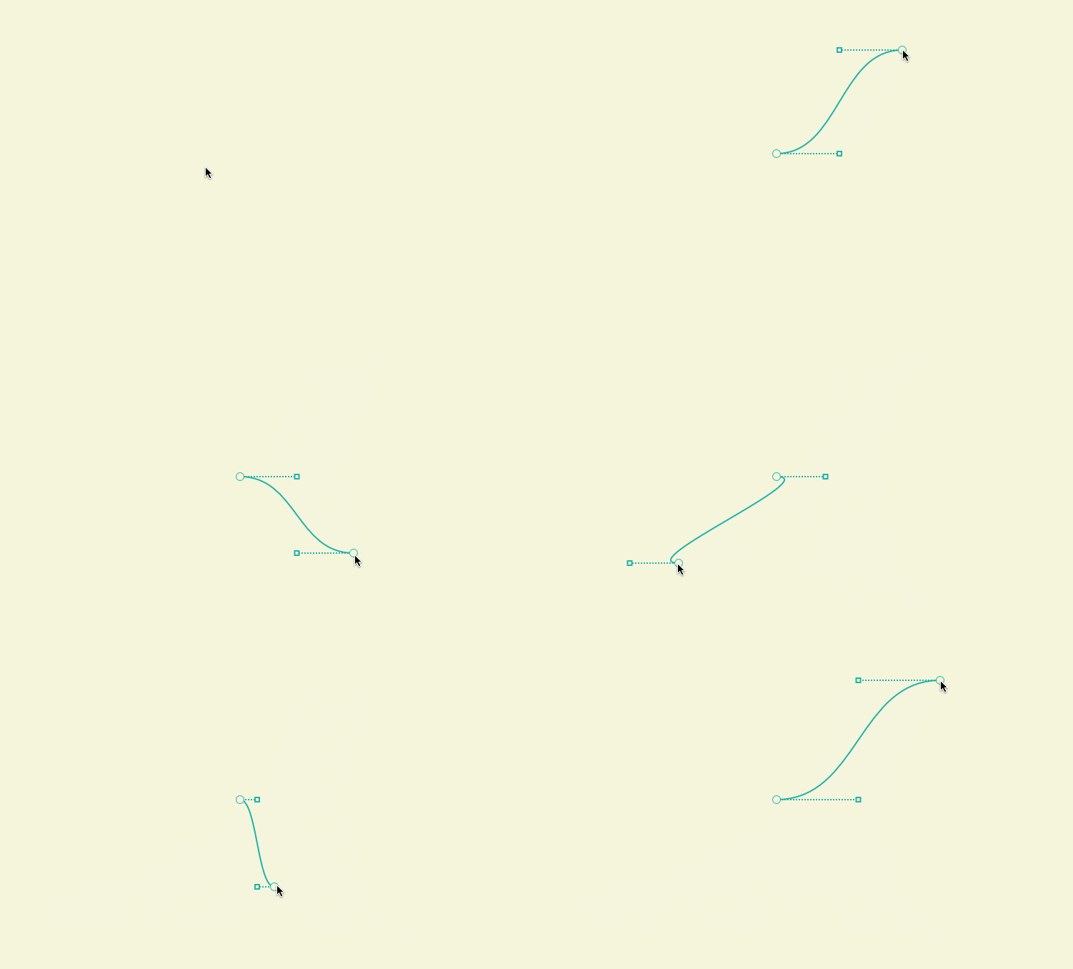
Say we are drawing a node graph and we need to connect two nodes with a Cubic Bézier. To create a Cubic Bézier, we already have the endpoints i.e. the predefined points within the node. What we need to calculate is the control points.
If you draw the tangent of the curve at the endpoints, you will see that the tangent is horizontal. It means that the curve is horizontal at the endpoints. To achieve this, the control point and its corresponding endpoint must lie on a horizontal line (i.e. their y-ordinate must be same). That makes matter more simple. We just need to calculate how far are the control points from their respective endpoints on the x-axis. To keep the curve uniform, I just calculate it the following way
var controlPointDistance = Math.Abs(endPoint1.X - endPoint2.X) / 2f;
Now that we have all the required points, we can render the bézier curve using the APIs provided by Windows. For example, using Win2d, you can create the curve in the following way
using (var pathBuilder = new CanvasPathBuilder(sender))
{
    pathBuilder.BeginFigure(endPoint1);
    pathBuilder.AddCubicBezier(controlPoint1, controlPoint2, endPoint2);
    pathBuilder.EndFigure(CanvasFigureLoop.Open);
    var geometry = CanvasGeometry.CreatePath(pathBuilder);
    drawingSession.DrawGeometry(geometry, Vector2.Zero, color, strokeThickness);
}
Using the above code you can render your own Bézier connector.

The source code for the sample project is available in GitHub.
Happy Coding!